


This document shares an “Overview of Weak Network Countermeasure Technologies for RTC Audio-Video Transmission.”
With the rapid growth of RTC (Real-Time Communication) audio-video technology, new applications emerge, penetrating various use cases. While cutting-edge technologies are driving substantial growth in online scenarios, user expectations for a better experience—lower latency, higher definition, and smoother playback—are escalating.
These three user-experience factors correspond to three core RTC metrics: real-time performance, clarity, and smoothness.
However, it’s often impossible to have it all. In scenarios requiring extremely low latency, video clarity may be sacrificed to ensure minimal delay, whereas scenarios emphasizing high definition might tolerate extra latency to secure higher-quality audio-video data.
To achieve better performance, we usually seek lower latency, higher clarity, and improved fluency through network transport optimizations. The main adversary here is the weak network, which causes congestion, packet loss, and jitter—major culprits behind poor user experience.
“Weak network countermeasure technology” is a broad term referring to strategies for addressing the aforementioned network deterioration and other network-related issues.
On the Choice of Transport-Layer Protocol (TCP/IP)
First, a brief introduction to transport-layer protocols:
In the TCP/IP layered model, the transport layer sits below the application layer and is typically provided by the operating system. It offers two principal protocols: TCP and UDP. TCP is a connection-oriented, reliable transport protocol that guarantees data integrity and ordering; UDP is a connectionless, unreliable protocol whose data reliability is left entirely to the application layer.
In real-time audio-video scenarios, using UDP first has become common practice across the industry, primarily because:
- TCP was not designed for real-time audio-video applications. Its built-in congestion and error-control mechanisms focus on reliability and throughput, leading to higher latency. Under poor network conditions, latency can increase dramatically. According to ITU Standard G.114, when end-to-end latency exceeds 400ms, user interaction is noticeably impaired.
- TCP’s congestion-control and error-control mechanisms reside in the operating system, which the application layer cannot optimize or adjust per scenario. This severely limits flexibility.
- UDP has less overhead than TCP, and transport-control strategies can be implemented entirely at the application layer, providing the flexibility real-time media often requires.
Hence, the weak-network challenges and countermeasures discussed here assume the use of the UDP protocol and, specifically, RTP/RTCP atop UDP, which is widely adopted in audio-video applications.
Primary Weak Network Issues and Corresponding Countermeasures
In essence, a “weak network problem” for audio-video transmission refers to adverse network conditions that undermine the user experience, chiefly network congestion, packet loss, and jitter. These problems cause stutters and poor real-time performance. Given the complex, heterogeneous nature of network environments, the severity of weak network problems can vary widely. Ensuring smooth communication under such conditions has always been a key focus in RTC.
Congestion Issues
When the traffic in the network exceeds the bottleneck capacity, congestion arises.
Congestion directly causes sudden packet loss or bursts of jitter. If the system fails to detect and respond (e.g., by reducing the send rate) quickly, receivers will see stuttering, high latency, or poor image quality.
To combat congestion, the primary approach is to design a “congestion-control algorithm” that promptly detects congestion and recovers from it as quickly as possible, thereby minimizing impact on the user experience.
1) Requirements for Congestion-Control Algorithms
RFC8836 comprehensively summarizes the needs of congestion-control algorithms for interactive real-time audio-video applications. A simplified overview:
- Latency: The algorithm should keep latency—particularly any latency it introduces—as low as possible while still providing feasible throughput.
- Throughput: Maximize throughput for the given scenario.
- Fairness: The algorithm should share bandwidth fairly with other real-time flows and TCP flows.
- Avoid “starvation”: Media flows should not starve or be starved by competing TCP flows.
- Convergence speed: The algorithm should reach a stable state as quickly as possible when a media flow begins.
- Network support: The algorithm should not rely on special network features.
- Stability: The algorithm should remain stable even when media flows change, for example, if a temporary interruption occurs in media transmission.
- Rapid response: The algorithm should swiftly adapt to changes in network conditions, such as bottleneck bandwidth or link-latency variations.
In short, congestion control faces two core tasks: (1) fast and accurate detection of network congestion, and (2) appropriate control measures to prevent or mitigate congestion and resume normal states quickly.
2) Congestion-Detection Algorithms
Congestion-detection algorithms can be divided into two categories based on measured indicators:
- Loss-based: Detect congestion by monitoring packet-loss events.
- Delay-based: Detect congestion by measuring delay variation.
For interactive, real-time audio-video applications, delay-based methods are often preferred, primarily because they detect congestion earlier—before serious packet loss occurs—and thus help avoid the quality issues associated with dropping packets.
Furthermore, loss-based methods often probe for link capacity by continuously increasing the send rate until packet loss occurs, which can lead to unbounded queueing delays in the network, especially where large buffers exist, sometimes causing multi-second latency spikes.
However, because delay-based methods react so quickly to latency increases, they can risk “starving” themselves when competing for bandwidth with loss-based flows. Proper strategies are needed to share network resources more fairly.
Delay-based methods generally use RTT (round-trip time) or OWD (one-way delay) measurements to gauge congestion. RTT measurement is more straightforward but includes reverse-direction effects that can mask forward-path congestion. OWD delay measurement avoids that.
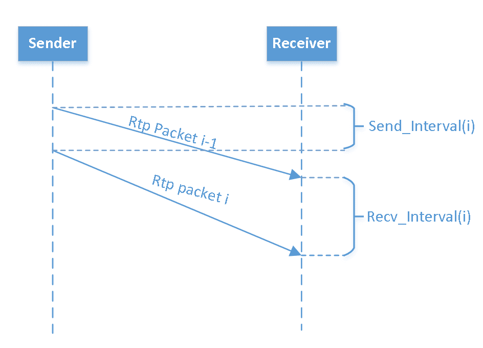
As shown in the figure, OWD is estimated by observing the differences between send intervals and receive intervals, indicating how queueing delays fluctuate.
3) Congestion Response Measures
In short, congestion response involves calculating an appropriate send rate based on the current congestion state. With regard to other weak network measures on the send side, possible rate-throttling methods include adjusting audio-video encoder rates, controlling Automatic Repeat Request bandwidth, or modifying FEC redundancy, which we explore later. If the sender is a forwarding node, then further strategies such as SVC layering or multi-stream adaptation may also apply.
4) A Typical Congestion-Control Framework
Below is the early congestion-control framework once used in Google’s WebRTC:
It adopts a hybrid sender- and receiver-driven approach. The sender uses a loss-based algorithm:
- If packet loss < 2%, increase sending bandwidth by 8%.
- If packet loss is between 2% and 10%, keep sending bandwidth unchanged.
- If packet loss > 10%, reduce sending bandwidth = current rate × (1 - 0.5 × loss).
The receiver uses a delay-based algorithm, estimating one-way delay with a Kalman filter, then combining that estimate with actual receive throughput to derive an optimal target bandwidth and feeding it back to the sender via RTCP. The sender then takes the minimum of the loss-based and delay-based estimates as the final target.
Below is WebRTC’s improved congestion-control framework:
Here, the entire congestion-control logic resides at the sender; the receiver merely provides measurement feedback.
The new framework refines the delay-estimation mechanism by applying linear regression to one-way delay variation. It discerns three trends—delay is rising, stable, or decreasing—and then uses that assessment along with the current send rate to determine the best target bandwidth.
In addition to refining detection, the new framework also introduces “proactive bandwidth probing,” further enhancing overall performance. It improves startup convergence as well as responsiveness to changing network conditions.
Packet Loss Issues
As noted, real-time interactive media typically runs over RTP/UDP, leaving packet-loss handling to the application layer.
From a network-transport standpoint, the primary techniques to handle packet loss are Automatic Repeat Request (ARQ) and Forward Error Correction (FEC). On the encoding side, depending on content or codec design, certain robustness features can offset loss—for instance, using B-frames in video encoding to reduce the impact of missing frames. Below, we focus on network-transport measures.
1) ARQ (Automatic Repeat Qequest)
In RTP/RTCP, the concept is straightforward: the receiver infers missing packets by gaps in sequence numbers and sends RTCP “NACK” requests for the sender to retransmit the missing data. The overall flow appears as follows:
When it detects a gap (say seq# 101 or 102), the receiver sends RTCP NACK(req 101, 102). The sender retransmits those packets, typically on a separate SSRC if possible.
Key details include:
- Initial request delay: Decide whether to request a missing packet immediately or wait—possibly factoring in FEC usage.
- Interval between repeated requests: For the same packet, do not resend the request before a full RTT elapses.
- Limit on total requests: Calculate the maximum allowable requests based on RTT and permissible overall delay.
- ARQ bandwidth limit: Automatic Repeat Request consumes part of total bandwidth and cannot exceed available capacity.
- Means of returning retransmitted packets: Sending them via a dedicated RTP SSRC is recommended, facilitating separate tracking of packet loss and ARQ bandwidth.
2) FEC (Forward Error Correction)
In real-time audio-video, FEC is widely used due to its immediacy in recovering from lost packets.
The fundamental idea is that the sender appends extra repair packets containing redundant data computed over source packets. The receiver then uses these redundancy packets to recover any missing source packets, as shown below:
Algorithms for generating repair data range from simple XOR-based methods to matrix-based or other coding techniques, which we will not detail here.
Below is the basic transmitting-side FEC framework:
Transmitter-Side FEC
“ADU” stands for Application Data Unit, i.e. an audio or video packet. The FEC encoder produces repair (redundancy) packets at a certain protection ratio. These repair packets, along with the source packets and metadata describing their protection relationship, are sent to the receiver.
Below is the receiving-side FEC framework:
Receiver-Side FEC
The receiver passes both source and repair packets to the FEC decoder. If any source packet is missing, the decoder reconstructs it using the available source and repair packets, then delivers the recovered audio-video data to the upper layer for decoding and playback.
In short, the “protection relationship” indicates which source packets each repair packet helps protect, typically signaled in a specialized format.
Under the RTP/RTCP framework, two standards define such formats:
- ULPFEC (RFC5109): “Uneven Level Protection,” which allows using different protection levels for more or less important packets.
- FlexFEC (RFC8627): “Flexible Forward Error Correction,” which supports both interleaved and non-interleaved parity-based FEC encoding for RTP packets.
3) Combining ARQ and FEC
Compared with FEC, ARQ’s shortcoming is added latency, but its advantage is higher bandwidth efficiency. Generally, the goal is to meet latency requirements while minimizing extra bandwidth and processing overhead for adequate protection.Hence, when combining ARQ and FEC, consider:
- Use ARQ under moderate latency constraints. Based on RTT and the max permissible latency, calculate the maximum number of retransmissions.
- If retransmissions alone can drive residual packet loss below ~1%, FEC might be unnecessary.
- If you do need FEC, the FEC protection ratio should be based on the residual loss probability after retransmissions, providing the final safety net.
Below is an example showing how ARQ and FEC might work together at different RTT values. For RTT < 20ms and max delay < 100ms, on a link experiencing 30% loss, ARQ alone can reduce loss below 1%. Thus, ARQ suffices here. As RTT grows, FEC coverage grows accordingly. Ultimately, under high RTT, FEC alone handles lost packets.
Jitter Issues
In short, jitter means variation in network delay over time. Greater jitter indicates more fluctuation in transmission delay.
Jitter causes stutter, skip-ahead playback, and other issues that severely impact the quality of audio-video communication. It arises from multiple sources—new flows competing for the same bandwidth, unstable send rates, and general network volatility.
A common approach is to compensate at the receiver with a Jitter Buffer, as shown below:
By introducing a “Jitter Delay,” the buffer homogenizes incoming data to enable smooth playback.
Estimating the optimal buffer delay is crucial. If it’s too large, it adds extra delay; if it’s too small, it won’t fully absorb the jitter. In WebRTC, Google employs different approaches for audio and video:
- Audio Jitter: The NetEQ module uses a histogram-based method with a forgetting factor, taking the 95th percentile of arrival intervals (Iat) as the buffer delay. This allows it to track variations over time while discarding outdated data.
- Video Jitter: WebRTC uses a separate approach. It measures variations in frame size and latency, applying a Kalman filter for dynamic delay estimation.
However, WebRTC is primarily designed for one-on-one calls. In multi-party conferencing scenarios with media forwarding nodes in between, the end-to-end latency variation can be different, so further optimizations may be needed.
Tencent RTC’s Weak Network Countermeasure Optimizations in Practice
TRTC (Tencent RTC) excels in weak network environments. Its core technical optimizations and real-world test data demonstrate high performance even under complex network conditions: global end-to-end latency stays under 300ms, packet loss tolerance exceeds 80%, and it manages jitter above 1000ms. Details of its weak network resilience are as follows:
1. Transport-Layer Optimization
By using a protocol stack based on UDP + RTP/RTCP, it avoids the queue blocking and congestion-control latency seen in TCP under poor network conditions.
Adopting an NACK retransmission mechanism: An NACK request is only sent upon detecting packet-sequence discontinuities, enabling precise retransmission of missing packets and reducing the round-trip latency overhead from frequent acknowledgments.
Integrating FEC (Forward Error Correction): A small number of redundant packets are added at the sender, allowing the receiver to recover missing packets from the redundancy and drastically lowering latency caused by waiting for retransmissions.
TRTC can flexibly switch between or combine ARQ (retransmissions) and FEC, adjusting the number of retransmissions and FEC overhead in real time based on network conditions.
2. Adaptive Bandwidth Control (QoS)
QoS dynamically measures packet loss rate, RTT, and jitter to predict available bandwidth in real time.
Based on these predictions, it adjusts encoder bitrate, FEC redundancy ratios, and retransmission rates, responding quickly to changes in network status and avoiding both congestion from overly aggressive transmission and wasted overhead from unnecessary redundancy.
3. Improvements at the Codec Layer
TRTC modifies the video-frame reference structure so it is no longer fully dependent on the “previous frame,” reducing the impact a single lost frame can have on the subsequent decoding process, and thereby bolstering packet loss resilience.
For audio, TRTC employs PLC (Packet Loss Concealment). When a loss is detected, it estimates and interpolates the missing samples from preceding and following audio frames, preserving natural sound quality even with high packet loss.
4. Jitter Buffer and Synchronization Strategies
By setting an appropriate Jitter Buffer at the receiver, TRTC dynamically adjusts buffer size based on arrival times and playback schedules, balancing minimal latency with jitter compensation.
It also provides an audio-video synchronization mechanism: detecting discrepancies and jitter between audio and video arrivals, then using variable-speed playback to align audio with video, mitigating the negative impact of desynchronization on the viewing experience.
5. Echo Cancellation and “Double-Talk” Optimization
Relying on Tencent’s in-house TRAE (Tencent Real-time Audio Engine), TRTC applies acoustic echo suppression (AEC) between the speaker and microphone to prevent acoustic echo loops.
It further optimizes “double-talk” scenarios (where both parties speak simultaneously), eliminating issues like feedback squeals and improving clarity so that both ends can hear each other distinctly.
6. Cloud-Side Decision-Making and Big Data Analysis
TRTC deploys a QoE (Quality of Experience) assessment framework, gathering packet loss, latency, MOS scores, and other metrics in real time to accurately gauge users’ subjective experiences.
The cloud decision system dynamically fine-tunes parameters for different users and networks, ensuring every participant receives the optimal transmission strategy and the best possible audio-video quality.
By orchestrating these multiple techniques, TRTC consistently delivers low-latency, high-quality performance in harsh network environments characterized by high packet loss and severe jitter, making it ideal for online education, remote work, interactive live streaming, and similar scenarios.

